![]()
Cisco Compatible SFP-50G-LR-S-FL Quick Spec:
Part Number: SFP-50G-LR-S-FL
 Fiber Optic Transceiver")
SFP-50G-LR-S-EXT-FL SFP-50G-LR-S-IND-FL SFP-50G-LR-S-FLT
SFP-50G-LR-S-EXT-FLT SFP-50G-LR-S-IND-FLT
Form Factor: SFP56
TX Wavelength: 1310nm
Reach: 10km
Cable Type: SMF
Rate Category: 10G/25/50GBase
Interface Type: LR
DDM: Yes
Connector Type: Dual-LC
Cisco Compatible SFP-50G-LR-S-FL Features
Support eCPRI wireless and 50GBASE-LR application
Comply with IEEE 802.3cd 50GBASE-LR
Comply with IEEE 802.3 50GAUI- 1 C2M electrical interface.
Management Interface comply with SFF-8472
Comply with SFF-8432 with duplex LC connector
Up to 10km transmission on SMF
2-wire interface with integrated Digital Diagnostic monitoring
DFB laser and PIN receiver
Support 10Gbps/25Gbps/26.5625GBd rate selection
Single +3.3V power supply
Power consumption lower than 2W
Operating temperature range:
Standard: 0°C to +70 °C
Extended -5°C to +85 °C
Industrial -40°C to +85 °C
Cisco Compatible SFP-50G-LR-S-FL Applications
25GBASE-LR
Product Description
The Cisco Compatible SFP-50G-LR-S-FL optical transceiver supports high-speed serial links over single- mode optical fiber at signaling rates up to 57.8 Gb/s PAM4 (the serial line rate of 64GFC). The product is compliant with Small Form Pluggable SFP+ industry agreements for mechanical and low-speed electrical specifications. High-speed electrical and optical specifications are compliant with ANSI Fibre Channel FC-PI-7.
The SFP-50G-LR-S-FL is a multirate 1310-nm transceiver that ensures compliance with FC-PI-7 64GFC, 32GFC, and 16GFC specifications. Per the requirements of 64GFC, internal clock and data recovery circuits (CDRs) are present on both electrical input and electrical output of this transceiver. These CDRs lock at 57.8-Gb/s PAM4, 28.05-Gb/s NRZ, and 14.025-Gb/s NRZ (64GFC, 32GFC, and 16GFC) accomplished by using two Rate Select inputs and I2C to configure
![]()
transmit and receive sides.
Digital diagnostic monitoring information (DMI) is present in the SFP56-10/25/50GBase-LR per the requirements of SFF- 8472, providing real-time monitoring information of transceiver laser, receiver, and environment conditions over an SFF- 8431 I2C interface.
Regulatory Compliance
Feature | Standard | Performance |
Electrostatic Discharge ( ESD) to the Electrical Pins | MIL-STD-883E Method 3015.7 | Class 1(>1000V for SFI pins, >2000V for other pins.) |
Electrostatic Discharge (ESD) to the Duplex LC Receptacle | IEC 61000-4-2 GR- 1089-CORE | Compatible with standards |
Electromagnetic Interference ( EMI) | FCC Part 15 Class B EN55022 Class B (CISPR 22B) | Compatible with standards |
Immunity | IEC 61000-4-3 | Compatible with standards |
Laser Eye Safety | FDA 21CFR 1040.10 and 1040.11 EN60950, EN (IEC) 60825- 1,2 | Compatible with Class I laser product. |
RoHS | EU 2015/863 | Compliant with exemption 7C(I) |
Cisco Compatible SFP-50G-LR-S-FL Absolute Maximum Ratings
The operation in excess of any absolute maximum ratings might cause permanent damage to this module.
Parameter | Symbol | Min | Max | Unit | Notes |
Storage Temperature | TS | -40 | +85 | ℃ | |
Operating Relative Humidity | RH | 10 | +85 | % |
Cisco Compatible SFP-50G-LR-S-FL Recommended Operating Conditions
Parameter | Symbol | Min | Typical | Max | Unit | Notes |
Operating Case Temperature | TOP | -40 | +85 | ℃ | I-temp | |
0 | +70 | ℃ | C-temp | |||
Power Supply Voltage | VCC | 3.135 | 3.3 | 3.465 | V | |
Power Dissipation | P | - | - | 2 | W | |
Data Rate | DR | 26.5625 | - | GBd | ||
Transmission Distance | TD | - | - | 10 | km | 1 |
Note:
Measured with SMF.
Cisco Compatible SFP-50G-LR-S-FL Optical Characteristics
All parameters are specified under the recommended operating conditions unless otherwise specified.
Parameter | Symbol | Min | Typical | Max | Unit | Notes |
Transmitter | ||||||
Center Wavelength | λC | 1304.5 | 1317.5 | nm | 1 | |
1300 | 1320 | 2 | ||||
Modulation Format | PAM4 | |||||
Average Output Power | P0UT | -4.5 | - | 4.2 | dBm | |
Outer Optical Modulation Amplitude | OMA | - 1.5 | - | 4 | dBm | |
TDECQ | TDECQ | 3.2 | dB | |||
Average Output Power ( Laser Off) | P0UT- OFF | - | - | -30 | dBm | |
Extinction Ratio | ER | 3.5 | - | - | dB | |
RIN15.6OMA | - | - | - | - 132 | dB/Hz | |
Optical return loss tolerance | - | - | - | 15.6 | dB | |
Transmitter reflectance | - | - | - | -26 | dB | |
Receiver | ||||||
Center Wavelength Range | λC | 1295 | 1311 | 1325 | nm | |
Damage threshold | - | - | - | 5.2 | dBm | 3 |
Average receive power | - 10.8 | 4.2 | dBm | |||
Receiver Power ( OMAouter) | - | - | - | 4 | dBm | 4 |
Receiver sensitivity ( OMAouter) | Max(–8.4, SECQ – 9.8) | dBm | ||||
LOS Assert | LOSA | -30 | - | dBm | ||
LOS De- assert | LOSD | - | - | - 11 | dBm | |
LOS Hysteresis | LOSH | 0.5 | - | - | dB | |
For C temp 0~70°C
For I temp -40~85°C
The receiver shall be able to tolerate, without damage, continuous exposure to an optical signal having this average power level. The receiver does not have to operate correctly at this input power
Measured with a PRBS31Q test pattern @26.5625 GBd, BER≤2.4X10^-4.
Cisco Compatible SFP-50G-LR-S-FL Electrical Specifications
Parameter | Symbol | Min | Typical | Max | Unit | Notes | |
Transmitter (Module Input) | |||||||
Differential Data Input Amplitude | VIN, P- P | 180 | - | 900 | mVpp | ||
Input Differential Impedance | ZIN | 90 | 100 | 110 | Ω | ||
Tx Fault | Normal Operation | VOL | -0.3 | - | 0.4 | V | |
Transmitter Fault | VOH | 2.4 | - | VCC | V | ||
Tx Disable | Normal Operation | VIL | -0.3 | - | 0.8 | V | |
Laser Disable | VIH | 2.0 | - | VCC+0.3 | V | ||
Receiver (Module Output) | |||||||
Differential Data Output Amplitude | VOUT,P - P | 300 | - | 1000 | mVpp | ||
Output Differential Impedance | ZO | 90 | 100 | 110 | Ω | ||
Rx LOS | Normal Operation | VOL | -0.3 | - | 0.4 | V | |
Lose Signal | VOH | 2.4 | - | VCC | V | ||
Cisco Compatible SFP-50G-LR-S-FL Digital Diagnostic Functions
Digital diagnostics monitoring function is available on FluxLight product. A 2-wire serial interface provides user to contact with module. It is compliant to SFF-8472 Rev10.2 with internal calibration mode. For external calibration mode please contact our sales stuff.
Parameter | Symbol | Min | Max | Unit | Notes |
Temperature monitor absolute error | DMI_Temp | -3 | +3 | ℃ | |
Supply voltage monitor absolute error | DMI_VCC | -3% | +3% | V | |
TX power monitor absolute error | DMI_RX | -3 | +3 | dB | |
RX power monitor absolute error | DMI_RX | -3 | +3 | dB | |
Bias current monitor | DMI_Ibias | -10% | +10% | mA |
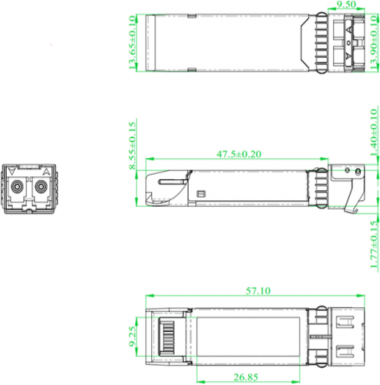
Mechanical Dimensions
Cisco Compatible SFP-50G-LR-S-FL Pin Assignment and Description
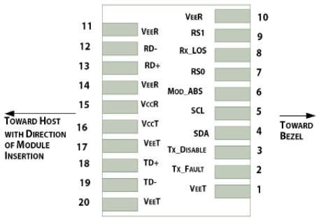
Contacts | Logic | Symbol | Description | Notes |
case | case | Module case | 2 | |
1 | VEET | Module Transmitter Ground | 3 | |
2 | LVTTL-O | TX_ FAULT | Module Transmitter Fault | 4 |
3 | LVTTL- I | TX_ DISAB L E | Transmitter Disable; Turns off transmitter laser output | 5 |
4 | LVTTL-I/O | SDA | 2 - wire Serial Interface Data Line( Same as MOD- DEF2 in INF-8074i) | 6 |
5 | LVTTL-I/O | SCL | 2 - wire Serial Interface Clock ( Same as MOD- DEF1 in INF-8074i) | 6 |
6 | MOD_ ABS | Module Absent, connected to VEET or VEE R in the module | 7 | |
7 | LVTTL- I | RS0 | Rx Rate Select | |
8 | LVTTL-O | RX_LOS | Receiver Loss of Signal Indication( In FC designated as Rx_ LOS and in Ethernet designated as Signal Detect) | 4 |
9 | LVTTL- I | RS1 | Tx Rate Select |
11 | VEE R | Module Receiver Ground | 3 | |
12 | CML- O | RD- | Receiver Inverted Data Output | |
13 | CML- O | RD+ | Receiver Non- Inverted Data Output | |
14 | VEE R | Module Receiver Ground | 3 | |
15 | VCC R | Module Receiver 3.3 V Supply | ||
16 | VCCT | Module Transmitter 3.3 V Supply | ||
17 | VEET | Module Transmitter Ground | 3 | |
18 | CML- I | TD+ | Transmitter Non- Inverted Data Input | |
19 | CML- I | TD- | Transmitter Inverted Data Input | |
20 | VEET | Module Transmitter Ground | 3 |
![]()
10
VEE R
Module Receiver Ground
3
Notes:
Labeling as inputs (I) and outputs (O) are from the perspective of the module .
The case makes electrical contact to the cage before any of the board edge contacts are made.
The module signal ground contacts, VeeR and VeeT, should be isolated from the module case.
This contact is an open collector/ drain output contact and shall be pulled up on the host. Pull ups can be connected to one of several power supplies, however the host board design shall ensure that no module contact has voltage exceeding module VccT/ R + 0 . 5 V.
Tx_Disable is an input contact with a 4.7 kOhms to 10 kOhms pullup to VccT inside the module.
2-wire interface.
The pins shall be pulled up with 4.7K- 10Kohms to a voltage between 3. 14V and 3.46V on host board
Cisco Compatible SFP-50G-LR-S-FL Rate Selection
Notes:
A2.73.bit 4 is default to 1b, RS0 and RS1 hardware pins state are ignored, module allows RS0(1) bits for 10G/25G rate selection
50G PMA4 Enable (A2.119.Bit2) | Soft RS0 select (A2.110.bit3) | Soft RS1 select (A2.118.bit3) | Rate (both Tx&Rx) |
0 | 0 | x | 10Gbps |
0 | 1 | x | 25Gbps |
1 | x | x | 50Gbps |
Pin Assignment
PIN # | Symbol | Description | Notes |
1 | VeeT | Transmitter Ground | |
2 | TX Fault | Transmitter Fault Indication | Note 1 |
3 | TX Disable | Transmitter Disable | Note 2, Module disables on high or open |
4 | SDA | 2-wire Serial Interface Data Line(Same as MOD-DEF2 in INF-8074i) | |
5 | SCL | 2 Wire Serial Interface Data Line (Same as MOD-DEF1 as defined in the INF-8074i) | |
6 | MOD-ABS | Module Absent,Connected to VeeT or VeeR in the module. | Note 3 |
7 | RS0 | SFP+ RX Rate Select, optional | Rate Select0,Not used.Note 9 |
8 | LOS | Loss of Signal | Note 4 |
9 | RS1 | SFP+ TX Rate Select, optional | Rate Select 1, Not used.Note 9 |
10 | VeeR | Receiver Ground | Note 5 |
11 | VeeR | Receiver Ground | Note 5 |
12 | RD- | Inv. Received Data Out | Note 6 |
13 | RD+ | Received Data Out | Note 6 |
14 | VeeR | Receiver Ground | Note 5 |
15 | VccR | Receiver Power |
Note 7, 3.3V 5% |
16 | VccT | Transmitter Power | Note 7, 3.3V 5% |
17 | VeeT | Transmitter Ground | Note 5 |
18 | TD+ | Transmit Data In | Note 8 |
19 | TD- | Inv. Transmit Data In | Note 8 |
20 | VeeT | Transmitter Ground | Note 5 |
Plug Seq.: Pin engagement sequence during hot plugging.
TX Fault is an open collector/drain output, which should be pulled up with a 4.7K–10KΩ resistor on the host board. Pull up voltage between 2.0V and VccT +0.3V. When high, output indicates a laser fault of some kind. Low indicates normal operation. In the low state, the output will be pulled to < 0.4V.
TX disable is an input that is used to shut down the transmitter optical output. It is pulled up within the module with a 4.7–10 KΩ resistor. Its states are:
Low (-0.3–0.8V):Transmitter on (>0.8, < 2.0V):Undefined
High (2.0–VccT+0.3V):Transmitter Disabled Open:Transmitter Disabled
Mod-ABS shall be pulled up with a 4. 7K–10KΩ resistor on the host board. The pull -up voltage shall VccT or VccR.
LOS (Loss of Signal) is an open collector/ drain output, which should be pulled up with a 4.7K–10KΩ resistor. Pull up voltage between 2.0V and VccR+0.3V. When high, this output indicates the received
optical power is below the worst-case receiver sensitivity (as defined by the
standard in use). Low indicates normal operation. In the low state, the output will be pulled to < 0.4V.
VeeR and VeeT may be internally connected within the SFP module.
RD-/+: These are the differential receiver outputs. They are AC coupled 100Ω differential lines which should be terminated with 100Ω (differential) at the user SERDES. The AC coupling is done inside the module and is thus not required on the host board.
VccR and VccT are the receiver and transmitter power supplies. They are de fined as 3.3V 5% at the SFP connector pin. Maximum supply current is 300mA. Recommended host board power supply filtering is shown below. Inductors with DC resistance of less than 1Ω should be used in order to maintain the required voltage at the SFP input pin with 3.3V supply voltage.
When the recommended supply filtering network is used, hot plugging of the SFP transceiver module will result in an inrush current of no more than 30 m A greater than the steady state value. VccR and VccT may be internally connected within the SFP transceiver module.
TD-/+: These are the differential transmitter inputs. They are AC -coupled, differential lines with 100Ω differential termination inside the module. The AC coupling is done inside the module and is thus not required on the host board.
Internally pulled down per SFF-8431 Rev 4.1.
Licensing
The following U.S. patents are licensed by Finisar to FluxLight, Inc.:
U.S. Patent Nos: 7,184,668, 7,079,775, 6,957,021, 7,058,310, 6,952,531, 7,162,160, 7,050,720