Quick Spec:
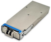
Form Factor: CFP2
TX Wavelength: 1310nm
Reach: 10km
Cable Type: SMF
Rate Category: 100GBase
Interface Type: LR4
DDM: Yes
Connector Type: Dual-LC Optical Power Budget: 6.3 dB
TX Power Min/Max: -0.6 to +4 dBm
RX Power Min/Max: -6.9 to + 4 dBm
Features:
Hot-pluggable CFP2 footprint LC duplex connector
Supports 103Gbps and 112Gbps aggregated signal
Single 3.3V power supply and power dissipation < 12W
Up to 10km transmission on SM fiber
Class 1 FDA and IEC60825-1 laser safety compliant
MDIO interface with digital diagnostic monitoring (DDM)
4x 28G electrical interface
Compliant with CFP2 MSA specification
RoHS6 compliant
Operating Case Temperature
Standard 0 to +70 °C
Industrial -40 to +85 °C
Applications:
100GBASE-LR4 Ethernet links
OUT-4
Overview
The CFP2-100GBase-LR4is a 100G transceiver module designed for applications over single-mode (SM) fiber with transmission distances of up to 10km. The module supports both 100GBASE-LR4 and OTU4 operation. It uses 4 WDM optical signals (around 1310nm), and multiplexes them into a single channel for 100Gbps optical transmission. Reversely, on the receiver side, the module optically de-multiplexes a 100Gbps LR4 input into 4 WDM channels signals, and converts them to electrical data. The central wavelengths of the WDM channels are 1295.56nm, 1300.05nm, 1304.58nm and 1309.14nm according to the IEEE LR4 recommendation. The module contains a duplex LC connector for the optical interface and a 148-pin connector for the electrical interface. The product is designed with form factor, optical/electrical connection and digital diagnostic interface according to the CFP2 MSA hardware specification.
Specifications
Functional Diagram
This product converts the 4x 28Gbps electrical input data into 4 channel WDM optical signals. The WDM light signals are combined by an optical MUX to a 103 or 112 Gbps data stream. The connector interface towards the SM fiber is LC. The receiver part accepts 103 or 112Gbps WDM optical signals and de-multiplexes them into 4 individual channels. Each wavelength is received by a photo diode (PIN) and converted into an electrical signal of 25Gbps or 28Gbps. Figure 1 shows the functional block diagram of this product.
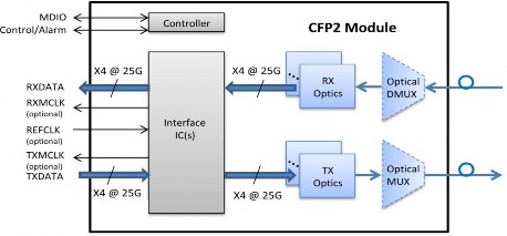
Figure 1. Functional diagram
Absolute Maximum Ratings
Parameter | Symbol | Min | Max | Unit |
Storage Temperature | Ts | -40 | +85 | °C |
Operating Case Temp (Standard) | TOP | 0 | 70 | °C |
Operating Case Temp (Industrial) | TOP | -40 | 85 | °C |
Power Supply Voltage | Vcc | -0.5 | 3.6 | V |
Relative Humidity (non- condensation) | RH | 5 | 85 | % |
Recommended Operating Conditions
Parameter | Symbol | Min | Typ | Max | Unit |
Power Supply Voltage | Vcc | 3.2 | 3.3 | 3.4 | V |
Power consumption | P | 12 | W | ||
Baud rate | 103 | 112 | Gbps | ||
Link Distance (SM fiber) | D | 10 | km |
Electrical Characteristics-Transmitter & Receiver (each lane)
Parameter | Symbol | Min | Typ | Max | Unit | Notes |
Transmitter | ||||||
Input Amplitude (Differential) | Vin | 150 | 1050 | mVpp | AC coupled inputs | |
Differential Input Impedance | Zin | 85 | 100 | 115 | Ohm | Rin > 100kOhm @ DC |
Receiver | ||||||
Output Amplitude (Differential) | Vout | 360 | 770 | mVpp | AC coupled outputs | |
Differential Output Impedance | Zout | 85 | 100 | 115 | Ohm | |
MDIO Interface Specification
Parameter | Symbol | Min | Typ | Max | Unit | Notes |
Input Voltage | VIH | 0.84 | 1.5 | V | ||
VIL | -0.3 | 0.36 | V | |||
Input Leak current | IIN | -100 | 100 | µA | ||
Output Voltage | VOH | 1.0 | 1.5 | V | ||
VOL | -0.3 | 0.2 | V | |||
Input Capacitance | CI | 10 | pF | |||
Input MDC Clock | fMDC | 0.1 | 4 | MHz | ||
MDC Clock Period | TMDC | 250 | 10000 | nsec | ||
MDIO Hold Time | Thold | 10 | nsec | |||
MDIO Setup Time | Tsetup | 10 | nsec | |||
GLB_ALM | Tglb_alm _ass | 150 | ||||
Tglb_alm _dea | 150 |
Optical Characteristics
Parameter | Symbol | Min | Typ | Max | Unit |
Lane Wavelength | L0 | 1294.53 | 1295.56 | 1296.59 | nm |
L1 | 1299.02 | 1300.05 | 1301.09 | ||
L2 | 1303.54 | 1304.58 | 1305.63 | ||
L3 | 1308.09 | 1309.1 | 1310.19 | ||
Signalling Speed per lane | 27.95 | Gbps |
Optical Characteristics-Transmitter
Parameter | Symbol | Min | Typ | Max | Unit | Notes |
Total Average Launch Power | PO | +10 | dBm | |||
Average Launch Power (each Lane) | Peach | -0.6 | +4.0 | dBm | ||
Side Mode Suppression Ratio | SMSR | 30 | dB | |||
Optical Return Loss Tolerance | 20 | dB | ||||
Extinction Ratio | ER | 4 | dB | |||
Transmitter Eye Mask Definition {X1, X2, X3, Y1, Y2, Y3} | G.959.1 Complaint | |||||
TX Disable Assert Time | Toff | 100 | µsec | |||
Optical Characteristics-Receiver
Parameter | Symbol | Min | Typ | Max | Unit | Notes |
Average receive power (each lane) | RPOW | -6.9 | 4 | dBm | ||
Receiver sensitivity per lane | Pmin | -8.4 | dB | |||
Maximum optical path penalty | 1.5 | dB | ||||
Optical Return Loss | ORL | -26 | dB | |||
LOS assert | LOSA | -19.4 | dBm | |||
LOS deassert | LOSD | -9.4 | dBm | |||
LOS hysteresis | LOSH | 0.5 | dB |