Quick Spec:
Form Factor: CFP
TX Wavelength: 1310nm
Reach: 10km
Cable Type: SMF
Rate Category: 100GBase
Interface Type: LR4
DDM: Yes
Connector Type: Dual-LC Optical Power Budget: 4.3 dB
TX Power Min/Max: -4.3 to +4.5 dBm RX Power Min/Max: -8.6 to +5.5 dBm
Features:
Hot-Pluggable CFP footprint LC duplex connector
Supports 103Gbps and 112Gbps aggregate
Single 3.3V power supply and power dissipation < 16W
Up to 10km transmission on SM fiber
Class 1 FDA and IEC60825-1 laser safety compliant
MDIO interface with Digital Diagnostic Monitoring (DDM)
CAUI electrical interface
Compliant with CFP MSA specification
RoHS6 compliant
Operating Case Temperature
Standard 0 to +70 °C
Industrial -40 to +85 °C
Applications:
100GBASE-LR4 Ethernet links
OTU-4
Overview
The CFP-100GBASE-LR4 is a 100G transceiver module designed for applications over single-mode (SM) fiber with transmission distances of up to 10km. The module supports both 100GBASE-LR4 and OTU4 operation. It uses 4 WDM optical signals (around 1310nm), and multiplexes them into a single channel for 100Gbps optical transmission. Reversely, on the receiver side, the module optically de-multiplexes a 100Gbps LR4 input into 4 WDM channels signals, and converts them to electrical data. The module has a Gearbox to aggregate 10x10G signals into 4x25G data-streams. The central wavelengths of the WDM channels are 1295.56nm, 1300.05nm, 1304.58nm and 1309.14nm according to the IEEE LR4 recommendation. The module contains a duplex LC connector for the optical interface and a 148-pin connector for the electrical interface. The product is designed with form factor, optical/electrical connection and digital diagnostic interface according to the CFP MSA Hardware Specification Revision 1.4.
Specifications
Functional Diagram
This product converts the 10-channel 10Gbps electrical input data into 4 channel WDM optical signals, using a gearbox. The WDM light signals are combined by an optical MUX to a 103 or 112 Gbps data stream. The connector interface towards the SM fiber is LC. The receiver part accepts 103 or 112Gbps WDM optical signals and de-multiplexes them into 4 individual channels. Each wavelength is received by a photo diode (PIN) and converted into an electrical signal which is then converted into 10-channel 10Gbps electrical output data. Figure 1 shows the functional block diagram of this product.
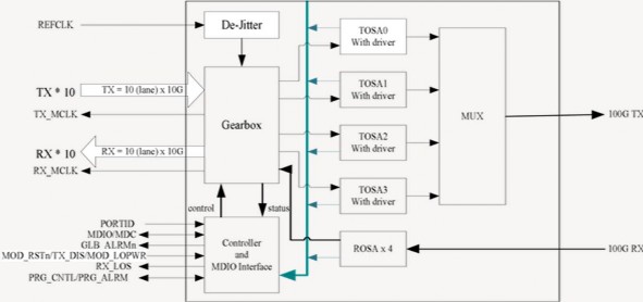
Figure 1. Functional diagram
Absolute Maximum Ratings
Parameter | Symbol | Min | Max | Unit |
Storage Temperature | Ts | -40 | +85 | °C |
Operating Case Temp (Standard) | TOP | 0 | 70 | °C |
Operating Case Temp (Industrial) | TOP | -40 | 85 | °C |
Power Supply Voltage | Vcc | -0.5 | 3.6 | V |
Relative Humidity (non- condensation) | RH | 5 | 85 | % |
Recommended Operating Conditions
Parameter | Symbol | Min | Typ | Max | Unit |
Power Supply Voltage | Vcc | 3.2 | 3.3 | 3.4 | V |
Power Supply current | 4000 | mA | |||
Power consumption | P | 16 | W | ||
Baud Rate | 103 | 112 | Gbps | ||
Link Distance (SM fiber) | 10 | km |
Electrical Characteristics-Transmitter & Receiver (each lane)
Parameter | Symbol | Min | Typ | Max | Unit | Notes |
Transmitter | ||||||
Input Amplitude (Differential) | Vin | 1050 | mVpp | AC coupled inputs | ||
Differential Input Impedance | Zin | 80 | 100 | 120 | Ohm | Rin > 100kOhm @ DC |
Receiver | ||||||
Output Amplitude (Differential) | Vout | 360 | 770 | mVpp | AC coupled outputs | |
Differential Output Impedance | Zout | 80 | 100 | 120 | Ohm | |
MDIO Interface Specification
Parameter | Symbol | Min | Typ | Max | Unit | Notes |
Input Voltage | VIH | 0.84 | 1.5 | V | ||
VIL | -0.3 | 0.36 | V | |||
Input Leak current | IIN | -100 | 100 | µA | ||
Output Voltage | VOH | 1.0 | 1.5 | V | ||
VOL | -0.3 | 0.2 | V | |||
Input Capacitance | CI | 10 | pF | |||
Input MDC Clock | fMDC | 0.1 | 4 | MHz | ||
MDC Clock Period | TMDC | 250 | 10000 | nsec | ||
MDIO Hold Time | Thold | 10 | nsec | |||
MDIO Setup Time | Tsetup | 10 | nsec | |||
GLB_ALM | Tglb_alm _ass | 150 | ||||
Tglb_alm _dea | 150 |
Optical Characteristics
Parameter | Symbol | Min | Typ | Max | Unit |
Lane Wavelength | L0 | 1294.53 | 1295.56 | 1296.59 | nm |
L1 | 1299.02 | 1300.05 | 1301.09 | ||
L2 | 1303.54 | 1304.58 | 1305.63 | ||
L3 | 1308.09 | 1309.1 | 1310.19 | ||
Signalling Speed per lane | 27.95 | Gbps |
Optical Characteristics-Transmitter
Parameter | Symbol | Min | Typ | Max | Unit | Notes |
Total Average Launch Power | PO | +8.9 | dBm | |||
Average Launch Power (each Lane) | Peach | -2.5 | +2.9 | dBm | ||
Side Mode Suppression Ratio | SMSR | 30 | dB | |||
Optical Return Loss Tolerance | 20 | dB | ||||
Extinction Ratio | ER | 7 | dB | |||
Transmitter Eye Mask Definition {X1, X2, X3, Y1, Y2, Y3} | G.959.1 Complaint | |||||
TX Disable Assert Time | Toff | 100 | µsec | |||
Optical Characteristics-Receiver
Parameter | Symbol | Min | Typ | Max | Unit | Notes |
Average Receive Power (each Lane) | RPOW | -8.8 | 2.9 | dBm | ||
Receiver Sensitivity per Lane | Pmin | -10.3 | dB | |||
Receive Overload per Lane | Pmax | 4.5 | dBm | |||
Optical Return Loss | ORL | -26 | dB | |||
LOS Assert | LOSA | -21 | dBm | |||
LOS Deassert | LOSD | -11 | dBm | |||
LOS Hysteresis | LOSH | 0.5 | dB |